Cool Things in the McMaster Catalog
 I bought and went through the entire print version of the McMaster-Carr catalog. 3824 pages. “Why the hell would you go through their entire catalog when they have such an amazingly-searchable-like-totally-better-than-even-Google website? Because you can’t be an as effective design engineer if you don’t have a basic knowledge of what’s out there and worth buying pre-fab’d, and what is worth designing on your own. I found quite a few things while going through the pages that I was not aware existed, or were just neat variations on things I did know existed, or which were just really awesome/impressive, even if I probably won’t ever end up using them. Many of the things I saw could come in handy to me in my engineering career, or in my tech related hobbies. I found about 90 items which I thought were neat enough to write down in my notebook, but I’ll just highlight a few of the coolest here (where “cool” is designed from the perspective of someone who is into machine design).
Rifle-Muskets
I have a mind to acquire a rifle for hobby target shooting and I’ve been reading up on the subject. During my move from Southern California to Washington to start my new job, I stopped in at Powell’s books in Portland, OR and was looking for a good “beginner’s guide to rifle purchasing.” I was quite happy to elicit curled lips from the unkempt hipster bookstore employees by asking for directions to their store’s firearms section… This is something which one simply does not do in the most enlightened looney-lefty anti-gun-nut city in our country.
Unfortunately I wasn’t able to find a “Dummies Guide to Rifle Buyin’,” but I did find an interesting book called “American Rifle, A Biography,” by Alexander Rose. It’s an interesting history of the development of the technology and the major innovators who drove it forward.
Mechatronics: The Major Subsystems
In just a couple weeks I’ll be starting my new mechanical engineering job with Electroimpact, a major aerospace tooling and automated machine production supplier (The video above is one of their automated fiber placement machines; it lays down carbon fiber tows on the mandrel barrel sections of the Boeing 787 fuselage). Since I have limited professional experience with CNC/mechatronics system design (beyond teaching simple design-build-test, kit-based projects to undergrads), I thought it would be appropriate for me to review the major subsystems which comprise the design space of a mechatronics-based engineering project.
Rather than focusing on the technical details of how to specify, design, and select and/or create individual components for each of these systems (which would be a diabolically large and unfeasible blog post), this write-up will just review the major subsystems–the “design building blocks”–of the technology which underpins CNC machinery & robotics–“mechatronics,” in the more general sense. This write-up will describe and then illustrate these subsystems with some specific examples. As an entry-level mechanical engineer, the field of mechatronics necessarily incorporates expertise which is beyond the realm of the knowledge which I possess at this point in my career. And, due to the inherent breadth of disciplines required in mechatronics system design, it will be quite a while–if ever–before I could comfortably write up a thorough explanation on specifying and designing components for all of these subsystems… Some of these subsystems are much better handled by Electrical Engineers, or engineers with a depth of experience in controls engineering.
Nevertheless, this write-up on mechatronics systems which has been written in broad brush strokes is outlined as follows:
- Mechatronics Defined
- Prime Movers
- Electrically Powered Actuation
- Linear Movement
- Electric Actuators
- Solenoids
- Shape-Memory Alloys
- Rotation
- Servos
- Stepper motors
- Linear Movement
- Mechanically Powered Actuation
- Linear Movement
- Pneumatic cylinders
- Hydraulic cylinders
- Rotation
- Air motors
- Hydraulic motors
- Combustion Engine
- Steam Engine
- Linear Movement
- Electrically Powered Actuation
- Motion Hardware
- Rolling-Element Bearings
- Ball Bearings
- Roller Bearings
- Needle Bearings
- Tapered Roller Bearings
- Spherical Roller Bearings
- Thrust Bearings
- Linear Bearings
- Linear Guide Blocks & Rails
- Ball Screws & Ball Nuts
- Plain Bearings
- Ball Joints
- Leadscrews
- Ballscrews
- Cams
- Gears
- Spur Gears
- Helical Gears
- Double Helical Gears
- Bevel Gears
- Hypoid Gears
- Worm Gears
- Rack & Pinion Gears
- Epicyclic / Sun & Planet Gears
- Belts & Pulleys; Chain & Sprockets
- Springs
- Rolling-Element Bearings
- Linkages & Structure
- Foundation
- Frames & Bedplates
- Four-Bar Linkages
- The “End Effector” / Tool
- Control Hardware
- Switches
- Relays
- PLCs
- Power Management Hardware
- Control Software
- Sensors
- Limit Switches
- Proximity Sensors
- Photoelectric Sensors
- Rotary Encoders
- Machine Vision
- Temperature Sensors
- Pressure Sensors
- References
Rear-view Mirror Dimmer
I drive a sedan on the roadways of California. I find the proliferation of trucks with jacked up lift kits and upgraded super-bright headlights in this state to be pretty obnoxious. The towering stature of these road-monsters puts their headlights right in line with my rear-view mirror, which blasts my night vision when driving in the evening (Note: I personally think that these trucks, as vehicles, are awesome. But another thing that annoys me about this situation is that most Southern Californians don’t even use them correctly–they buy them as mechanical-codpiece-status-symbols. If I bought one, I’d actually run the truck through some mud once in a while. The majority of Southern Californians don’t understand that that is what they are for.).
Fortunately for sedan owners, automotive and optics engineers are smart enough to supply a simple solution to this problem with most cars–the rear-view mirror dimmer. In many cars, this is simply a mechanical toggle switch at the base of the mirror. But I was curious, how does this switch make the image behind you dim?
This rear-view mirror dimmer relies on two things:
- The optical properties of “mirror glass” and “mirror silver”–namely: the silver has a much higher reflectivity value than the mirror glass, and,
- The mirror silver surface and the mirror glass surface are not parallel.
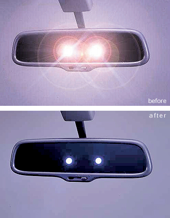
In the “flipped-down position” of the toggle switch, the rear-view mirror functions as a typical mirror–objects behind your car are reflected to your eye off of the mirror silver backing:
But while in the “flipped-up position,” the mirror is rotated up and the plane of the silver mirror backing is oriented so that it no longer reflects the image into your eyes (instead, this image is reflected up to the ceiling of your car, or down to the floor, depending on the design). In the “dimmed” case, the image behind your car is reflected off of the mirror glass surface:
If you have seen the outline of your reflection in a clean glass surface, you know that the intensity of the image is very faint and this is exactly what optics engineers count on when designing the “dimming” feature of a rear-view mirror. By reflecting the image to your eye off of the glass surface–which has much lower reflectivity–the jackass behind you is far less able to blind you.
Given the number of times I use this feature in my car, the “rear-view mirror dimmer” is a valuable mechanism without qualification.
Riveting
Having recently landed a mechanical engineering position which I’ll start on May 24th with an aerospace tooling and machine supplier, I think it’s appropriate to review riveting. A very large portion of their business consists of electromagnetic riveting guns coupled to automated riveting process machinery.
- Overview
- Definition & Description
- Installation Methods
- Hot-Formed
- Cold-Formed Deformation
- Mechanical Forming
- Benefits
- Drawbacks
- Applications
- Rivet Designs
- Solid Rivets
- Semi-Tubular Rivets
- Blind Rivets
- Joint Design; Strength & Fatigue
- Forms of Rivet Joints
- Specification of Rivets; Design Parameters
- Strength Calculation
- Fatigue
- References
Slow-Motion Bullet Impacts (Video)
This is a very impressive video made by someone named Werner Mehl, who is either an employee of–or used high speed video equipment supplied by–a German company called Kurzzeit (which my rusty German tells me is English for “short-time”).
It’s particularly interesting how the rifling deformation on some of the bullets causes them to split preferentially along the direction of the rifling.
Dynasplint
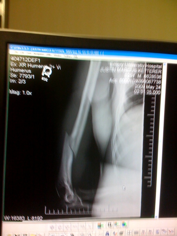
Almost a year ago, I broke the humerus in my right arm:
True Life: I did this arm wrestling with an old housemate… “Arm wrestling? Sure, I haven’t done that in forever, what’s the worse that could happen?”
While the bone was healing, my arm was in a sling for five weeks. I learned to be pretty good at one-handed typing with my left hand, since I was submitting my master’s thesis in four weeks. After getting my arm out of the sling, I had lost quite a bit of my range of motion. I could not extend my arm because the bicep and connective tissue had become so taught from being held up in the sling for so long:
 Shortly after getting out of the sling. (Coke museum in Atlanta with my sister).
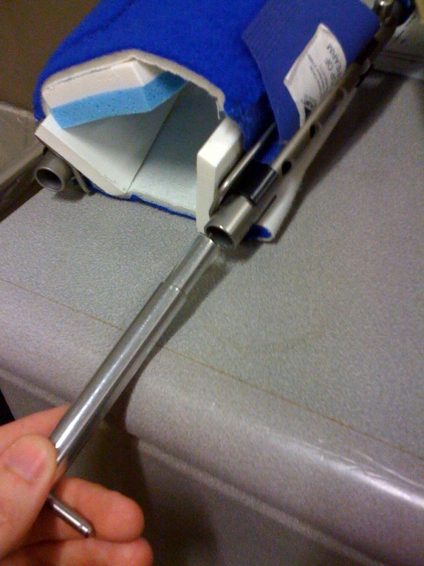
I was distraught to see how messed up (and weak) my arm had become. Fortunately for me, help was on the way IN THE FORM OF TECHNOLOGY. My physical therapist hooked me up with a Dynasplint rental. A Dynasplint is basically a medieval torture device in which you crank down on some springs with a key which then forces your arm (or leg or jaw(?) etc) to stop misbehaving, and extend like normal.
The Dynasplint representative said I should have worked up until I was able to wear it all night while sleeping but this thing HURTS LIKE HELL. The rental was pricey but definitely worth it–I’m pretty sure that the Dynasplint did more to help me regain something close to my original range of motion than sessions with the physical therapist did. I’ll mention again that it HURTS LIKE HELL. I don’t think I ever made it much beyond an hour and fifteen minutes wearing the device. The pain would just increase as time wore on while wearing it too–it was nuts. I definitely never fell asleep wearing the Dynasplint, but the pain was worth getting my range of motion back. And, after about five months in the gym, I was back to my pre-break weight lifting strength too.
 Getting medieval on my misbehaving arm
Due to the construction of the thing, I couldn’t really tell how the springs in the design worked on your arm. There might be powerful clock springs in the elbow joints on either side of your arm, and cranking on the key was what tightened them.
 The key for tightening the springs is inserted at the “hand end” of the forearm rod
Alternatively, linear springs in the forearm rods may have connected to a feature in the elbow joint which was offset from the center of the elbow pivot point to provide the necessary torque. I’m just not sure–too much of the hardware was hidden under the rods and joints. The designers were smart to provide a graduated tension scale in the forearm rods on both sides of the forearm rods in order to allow the user to make sure that the torque was equal on both sides of the arm:
I highly recommend the Dynasplint for anyone fresh off of breaking a bone and is in physical therapy, trying to regain range of motion. With pain comes gain, and I attribute getting most of my elbow extension back to the Dynasplint.
Autorotation
I was watching the movie “Road Warrior” yesterday on Netflix (which probably qualifies as required viewing for anyone who digs the science fiction genre). I was intrigued by a helicopter-looking machine in the movie which looked a lot like that shown in the video above.
What really puzzled me about this helicopter-like machine was the spindly, relatively unsupported structure supporting the main rotor. Helicopters with powered main rotors usually have beefy structures supporting the main rotor for transmitting engine torque and adjusting the pitch of the blades to maneuver the aircraft. But this machine didn’t even look like power was being transmitted from the engine to the main rotor; this made me wonder, “How the heck is this thing being held aloft without a powered main rotor; and how is the main rotor even spinning then?”
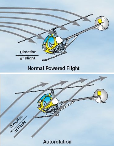
As it turns out, there is actually a class of machines that do have unpowered main rotors which are still providing lift for the vehicle and they are called Autogyros. They rely on a principle called autorotation, which is a term for the aerodynamic effect of air rising up through the main rotor, as opposed to being drawn down through the rotor, as helicopters do when moving forward in flight.
Air rising up through a rotor can force a properly designed airfoil to spin and provide lift. While the principle of autorotation is the method by which helicopters can land safely if engine power is lost, it also can be exploited to provide lift for a machine whose main rotor is not powered by an engine at all, and this is what autogyros do.
By angling the main rotor backwards, so that air is forced up through the rotor while in forward flight, the main rotor is both forced to rotate by the motion of forward flight through the air, while simultaneously providing lift.
 Image above: main rotor angled backwards clearly displayed here. Rear rotor provides forward thrust required to force air up through main rotor.
As the wikipedia article on the principle of autorotation explains, different regions along the span of the main rotor blades serve different purposes:
- Driven Region: aerodynamic drag on this portion of the blade provides lift, but counteracts torque on the rotor, slowing it down.
- Driving Region: net aerodynamic thrust on this portion of the blade provides the force which forces the rotor to rotate.
- Stall Region: blade in this region is stalling–i.e., operating above max. angle of attack, causing drag, and slowing the rotor down.
To simplify a very complex aerodynamics problem: by adjusting the pitch on the rotor blades, the ratios of the three regimes are adjusted and this alters the net forces acting on the vehicle which enables maneuvering. I thought this was a pretty unique application of aerodynamic principles in an uncommon method of flight, similar to the Fanwing I discussed earlier.
Welding
Several of the companies I’m currently pursuing for interviews rely on welding for some portion of their operations, so I wanted to refresh that technology in my mind. Welding is defined as “a materials joining process in which two or more parts are coalesced at their contacting surfaces by a suitable application of heat and/or pressure [1].” Fusion welding–in which heat is used to melt and join the base materials with a filler metal sometimes added–is described here. Solid-state welding is less common, but includes diffusion welding (two surfaces held together under pressure at high temperature, allowing atomic diffusion/fusion to occur), friction welding (friction between the two surfaces generates the heat for coalescence), and ultrasonic welding (moderate pressure is applied between the parts while an ultrasonic oscillation parallel to the contacting surfaces achieves atomic bonding) [1]. The following post will be divided into the following sections:
- Surface Preparation
- Weld Joint Geometry
- Safety
- The Various Welding Technologies
- Oxyfuel
- Oxyacetylene
- Arc Welding
- Consumable Electrode
- Shielded Metal Arc (stick welding)
- Gas Metal Arc
- Submerged Arc
- Nonconsumable Electrode
- Gas Tungsten Arc (TIG)
- Resistance Welding
- Resistance Spot Welding
- Resistance Seam Welding
- Resistance Projection Welding
- Heat Sealing
- Oxyfuel
- Design Factors; Strength & Fatigue


