Riveting
Having recently landed a mechanical engineering position which I’ll start on May 24th with an aerospace tooling and machine supplier, I think it’s appropriate to review riveting. A very large portion of their business consists of electromagnetic riveting guns coupled to automated riveting process machinery.
- Overview
- Definition & Description
- Installation Methods
- Hot-Formed
- Cold-Formed Deformation
- Mechanical Forming
- Benefits
- Drawbacks
- Applications
- Rivet Designs
- Solid Rivets
- Semi-Tubular Rivets
- Blind Rivets
- Joint Design; Strength & Fatigue
- Forms of Rivet Joints
- Specification of Rivets; Design Parameters
- Strength Calculation
- Fatigue
- References
Overview
Definition & Description
A rivet can be defined as a permanent mechanical fastener. It is a fastener–unlike say, welding, it does not chemically merge the materials of the subcomponents. It is also permanent–unlike a threaded bolt, rivets are deformed into place in holes within the subcomponents to achieve a permanent connection (though some of them can be removed with relative difficulty).
Rivets come in many forms, and the different types will be described below in the “Rivet Designs” section.
Installation Methods
There are three general types of rivet installation methods. Which installation method is used on what rivet depends on the design of the rivet itself.
Hot-Formed
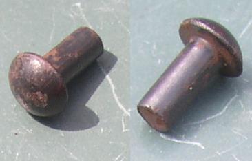
In hot-forming of “solid rivets,” the rivet is heated to a red-hot, malleable state, slid into the workpiece, and the end of the rivet composed of a cylindrical shaft is then “upset” into a headed shape.
 (above) Solid rivet before hot-forming
 Solid rivet after forming, joining two steel plates
Hot-forming of rivets is old-school, and rarely used now. The process was labor-intensive, requiring several workers:
- The two components to be joined are fixtured in position. A hole is drilled (or punched and/or reamed) if one hasn’t been already.
- One worker slides a red-hot rivet in place from the rivet furnace (occasionally, the “rivet catcher” is a completely different job from the worker tending to the furnace).
- One worker hammers on the rivet to create the “factory head” while another worker holds the factory head in place with a “bucking bar.”
(And back in the day, a guy wouldn’t have had the benefit of a pneumatic hammer, either. He’d have to bash on it with a mallet.)
Old bridges, boilers, and ships were made in this way. I recently visited the Queen Mary cruise ship (operated from 1936-1967, now docked in Long Beach California as a tourist attraction). I was kind of in awe of how much tedious riveting was required to assemble this immense ship (which is even larger than even some modern cruise liners; image source):
Pneumatic and hydraulic machines have been created to make hot-riveting (and cold-riveting, too) a much less labor-intensive process, but the nature of the hot-riveting process–having to run a rivet immediately from a hot furnace into the workpiece–does not make it easy to automate.
Things that I would be particularly concerned about if I had to design with this fastening method include:
- A solid understanding of the heating/cooling cycle during the installation of the rivet would be necessary. This heating could alter the rivet metal microstructure and thus, the mechanical properties of the rivet.
- Largely a manual process… The process variables of heating time, differences in strength or ability across workers could affect the final upset shape of the rivets and the joint performance. Bolted connections (which do not require expensive skilled labor) have almost completely replaced riveting in structural steel construction for this reason… The hot-riveting process has become irrelevant enough that steel construction codes do not even contain design practice recommendation for riveting anymore [2].
- Slow. It’s a slooooowww process.
Cold-Formed Deformation
The process required to buck a rivet into shape is significantly easier if the rivet does not need to be heated. Modern rivets exploit optimized geometry and careful material selection to avoid the necessity of heating the rivet to allow it to be formed into shape. Rivet materials are selected which are ductile and tough, and the rivet dimensions are engineered to allow the “factory head” of the rivet to deform into shape without rupturing during this cold working process.
A great example of this is the electromagnetic cold forming process which the company Electroimpact was founded on (good paper on this technology is located here, which is where the description and images below were taken from):
LVER (low voltage electromagnetic riveting) is based on eddy current repulsion between a copper pancake coil and a copper driver plate. Two actuators are typically employed on opposing sides of the rivet. Each actuator is connected to its own capacitor bank by a coaxial pulse cable. After the capacitors have been charged to a predetermined voltage, this stored energy is discharged through the coil. An intense magnetic pressure quickly develops between the coil and the driver plate, accelerating the driver into the rivet. Peak forces of over 30,000 lbs can be reliably and accurately generated using this technology.
Wild!
Mechanical Forming
Many types of cold-formed rivets rely on design features of the rivet–such as breakaway mandrels inside tubular rivets (so-called “pop rivets”)–to deform the rivet into shape. These rivets, rather than relying on the standard externally applied compressive force to create the “factory head,” employ extra hardware which is part of the rivet and assists in bucking the rivet. Rivets with these unique features will be discussed in the “Rivet Designs” section below.
Benefits
- Appropriate where vibration can threaten loosening of bolted assemblies
- Relatively strong and lightweight
- Lends itself to automation (cold rivets on reels or fed via pneumatic feeders, combined with automated drills)
- Joining dissimilar materials (tough to do with welding)
Drawbacks
- Disassembly is complicated
- Joint is not quite as neat as a welded structure
- Understanding of joint stress behavior can be complicated
Applications
Some applications of riveting include
- Aerospace assembly–riveting is lightweight and high strength [2].
- Fastening components made of metals which are difficult to weld.
- Fastening components of dissimilar metals.
- Pocket knives–the axis which the blades pivot on.
Rivet Designs
Solid Rivets
Solid rivets were illustrated earlier:
The cylindrical end of the shank must be deformed by an external mechanical force to form the “factory head.” Solid rivets are used where reliability and safety are required [2], and thus they are heavily used in the aircraft industry. Rivets do not have to have the rounded head (“universal” rivets) as illustrated above–another popular version has a 100 degree countersink. Popular materials for aircraft rivets include aluminum alloys, titanium, and nickel-based alloys (e.g., Monel); some types of aluminum need to be annealed before they can be bucked, to prevent splitting [2]. A disadvantage of these rivets is that both side of the rivet have to be accessible for assembly.
Semi-Tubular Rivets
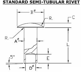
Semi-Tubular rivets are much easier to install than solid rivets because the shank which protrudes beyond the back of the second workpiece is hollowed out, which allows it to be bucked much more easily:
Besides being much easier to buck, the semi-tubular rivet prevents the solid part of the shank from expanding in the hole–solid rivets expand in the hole during the bucking process, typically forming an interference fit (hot formed rivets can contract in the hole, leaving a gap). Thus, semi-tubular rivets can be used as pivot points. The bucked end of a semi-tubular rivet will have a rolled-over shallow dimple in it.
Another unique type of semi-tubular rivet is the “self-piercing rivet,” which is sold by (among others) Emhart teknologies–check their website for a good video (.wmv) of the process. The self-piercing rivet is semi-tubular and punches through the upper metal, but an anvil below compressed below the rivet and workpieces then forces the lower sheet metal to deform around the legs (which flare outwards from the shape of the anvil) to form a water and gas tight seal.
Blind Rivets
One major drawback about most rivet designs is that they require access to both sides of the workpiece–the factory head has to be held in place while the opposite end of the rivet is bucked into the “shop head” shape. This is not true with “blind rivets.” Blind rivets can be inserted and bucked with access to only one side of the panels being joined. Their design typically incorporates a “mandrel” running through the center of a tubular rivet which draws and compresses the rivet into shape when the mandrel is pulled or threaded out of the rivet. Manufacturers have different methods of achieving this form of rivet.
Several types of blind rivets are also made by Emhart teknologies, the most common being the “POP” rivet. In the POP rivet, the mandrel is pulled through the center of the rivet. The mandrel has a notch which causes most of the mandrel to snap off at a controlled load, leaving a small bead of metal in the shop head of the rivet. (I used this type of rivet in the construction of my senior capstone design project–the “Sparty Tank” remote control t-shirt launcher–described in the undergrad design portfolio here):
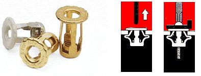
These rivets are not used frequently in aircraft [2] because of the possibility of the bead of metal falling out of the shop head, causing the joint to loosen. Also, tubular rivets in general are weaker than solid rivets. However, some tubular rivets leave a significant portion of the mandrel inside the rivet, and these have a better shear strength than those which remove the mandrel completely [3]. The “well-nut” by Emhart relies on elastomeric material that deforms outward when a threaded bolt is run into it (thus, perhaps technically disqualifying it from the status of “rivet”).
A third type of rivet by Emhart–the popnut–may not be able to be defined as a rivet either, since it involves a threaded connection. However, it consists of a threaded insert installed into (typically) a single base piece. A drill-like tool with a threaded, bolt-like bit installed pulls the popnut in and causes the grooved barrel section of the fastener to collapse, forming a ring of material securing the popnut into the workpiece:
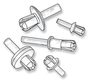
Another type of blind rivet design [a “trifold”] available from Emhart and is, again, really intended for a threaded bolt connection only (though it is available from other suppliers without the necessity of a threaded inner ring, i.e, you can buy a traditional rivet in the form of a trifold). Called a “jack nut,” by Emhart, it relies on three flared legs expanding outwards, with a threaded inner ring for threading a bolt into, to attach the other workpiece. A tri-fold rivet is good where a distributed load is required–spreading it across the wide area formed by the compressed legs.
Another form of blind rivet is the “drive rivet” which has a short stub protruding above the factory head. Tapping on the stub with the hammer forces the mandrel shaft down through the middle of the rivet, expanding the legs or other features on the back of the rivet to fasten the workpieces. Drive rivets have relatively weak clamping forces compared to other rivet types [2].
Joint Design; Strength & Fatigue
Forms of Rivet Joints
There are two basic types of rivet joints. One is the lap joint, where the two workpieces overlap each other and the rivet goes through both of them. The second type of rivet joint is the butt joint, which requires a “cover plate” or “butt strap” to attach the rivets to, and which spans the butt joint edge. A butt joint has the advantage of a smooth outer plane and a less complex loading state on the joint (lap joints introduce twisting into the joint due to the workpieces terminating in different planes).
 Above: single riveted lap joint
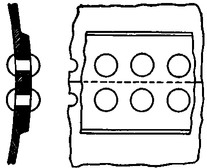 Above: single riveted butt joint with butt strap
The images above display “single riveted” joints, but it is quite common to have multiple rows of rivets in lap or butt joints.
The spacing between rivets in a single row is termed “pitch,” and the spacing between rows of rivets is termed “back pitch” or “transverse pitch.” The spacing between rivets in adjacent rows is called “diagonal pitch.” The distance from the edge of the plate to the nearest row of rivets is called “margin.” [1]
Specification of Rivets; Design Parameters
- Type of joint (lap or butt)
- Spacing of rivets (some general guidelines provided below)
- Type and size of rivet (solid rivet? blind rivet? general guidelines on sizing of rivets provided below)
- Type and size of hole (countersink or button head rivet being used? holes typically drilled 1/16″ larger diameter for hot driven rivets, but reamed for minimum clearance for cold-driven rivets)
- Rivet material (weight considerations, safe-failure considerations).
Strength Calculation
Some of the assumptions of bolted joint strength calculation are transferable to rivet joint calculation. However, a major difference between the two is that tensile loads transmitted through rivets at say, a lap joint, are computed as transferred through the rivets in shear. While this is not entirely true for hot rivets (which, on cooling, contract and apply a compressive force at the interface) or in situations where a solid understanding of the clamp force during riveting is known, this is definitely different than the behavior of a bolted joint. Bolted joints, when properly designed and installed, rely on interfacial static friction shear to bear a tensile load transverse to the axis of the bolt. This interfacial shear is due to the clamping force applied by the bolt when it is torqued down. Only a bolted joint that is not installed properly, with the nut not torqued down at all, would cause the load to be imposed on the bolt in shear.
Rivets should NOT be combined with bolts in creating a fastening assembly. Particularly with rivets that expand to fill the hole with an interference fit, they provide different joint mechanics than bolted connections. Due to the interference fit, they will bear the loading on the joint earlier and thus fail earlier than bolts… Therefore, assuming the load is shared evenly between a set of rivets and bolts is invalid. The rivets will fail first and the joint will then “unzip”–the bolts will immediately fail due to the immediate transfer of high load.
As a general design guideline, the rivet diameter commonly falls between:
1.2√(t) < d < 1.4√(t)
Where “t” is the thickness of the plate [1].
To design a rivet joint for strength, several assumptions are made, which are analagous to a few of the assumptions made in bolted joint design [1].
- Load is carried equally by the rivets.
- No combined stresses act on a rivet to cause failure (engineering judgement is required to determine if this is a safe assumption).
- The shearing stress in a rivet is uniform across the cross-section under question (this is an unconservative assumption if a thorough analysis is to be performed and strength knockdown parameters should be employed which account for stress concentrations at the top of the rivet and hole which would cause the shear-stress field to be anything but uniform).
- Load causing failure in single shear would need to be doubled to cause failure in double shear.
- The bearing stress of rivet and plate is distributed equally over the projected area of the rivet (another unconservative assumption which should be accounted for by determining stress concentrations on the rivet and plate-hole joint assembly, which cannot possibly be line-to-line fit-up).
- The tensile stress is uniform in the section of metal between rivets (again a generous assumption; K [stress concentration factor] is known to be 3x the the far-field stress at the edge of a hole–compute accordingly).
Allowable stresses for rivet design calculations relating to steel construction and boiler manufacture are specified in their respective codes. In the case of aerospace, qualification for a specific rivet design is an experiment-intensive process (while I was working on my master’s degree at GA Tech, a couple grad students in my lab were doing these sorts of tensile testing experiments).
When the center of the rivet is placed a minimum of 1.5x its own diameter away from the edge, the “shearing of plate,” and the “tearing of plate to margin” failure modes (in the picture above) are prevented. If that design practice is followed, a simple analysis of rivet strength is then performed by analyzing three different failure modes:
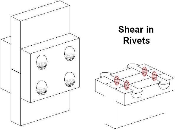
Rivet Shear
This computation is performed to predict failure for modes of “single shear of rivet” and “double shear of rivet” illustrated above. The shear strength of the rivet material must be known (or yield strength, depending on what you are computing for). This calculation is based on assumptions (2) and (3) above.
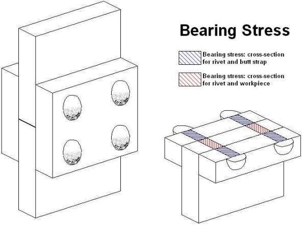
Bearing Stress
To predict failure for the case illustrated as “crushing of plate or rivet” in the “failure modes” picture above. The compressive failure strength (or, a more sensible calculation for materials in compression: yield strength) for the plate and rivet materials must be known. This computation is based on assumption (5) above. For the case illustrated below (single riveted, double butt-joint), whichever of the two cross-sectional areas is smaller will be the one which is pertinent to the calculation of bearing stress on the rivet.
Plate Stress
This computation is performed to predict failure of the plate area between the rivet holes (or the area of the butt straps if it is a butt joint)–the failure modes described as “tearing between rivets” in the “failure modes” picture above. This computation is based on assumption (6) above. If the workpiece plate and butt strap are the same material, then computation only needs to be performed for the smaller of the two cross-sectional areas.
Below, an image is taken out of reference [1]. Equations have been derived and compiled in books which save the engineer the necessity of computing the stress distribution for common rivet patterns.
Fatigue
Given the aforementioned caveats to the assumptions in just a simple monotonic strength calculation, an in-depth understanding of the specific details of any rivet design will be required for any rivet joint subject to fatigue. Where appropriate, sub-units of repeating rivet patterns can be modeled in fatigue, just as they can be for static strength analysis. Traditional fatigue analysis methods can be used to predict fatigue of riveted joints, but a strong understanding of the specific rivet and specific joint behaves will be required–are the rivets subjected to shear, or is the clamping force making it perform more like a bolt? Is the rivet material more prone to fatigue damage, or the base workpiece metal–and which would make more sense to have fail, in order to allow for a “fail safe” design, or one that can allow early damage detection?
References
1. “Machinery’s Handbook, 28th Ed.,” Erik Oberg, Franklin Jones, Holbrook Horton, Henry Ryffel, c. 2008 Industrial Press New York, 2692 pages
2. http://en.wikipedia.org/wiki/Rivet (nothing used from Wikipedia was used without corroboration from the other, “more serious” engineering sources)
3. “Marks’ Standard Handbook for Mechanical Engineers, 11th Ed.,” E. A. Avallone, T. Baumeister III, Ali M. Sadegh, c. 2007 McGraw Hill
One final treat… A youtube video of an esoterically oddball rivet that (according to the video description) was once used to repair WWII airplanes in the field–it deforms from explosive chemicals ignited in its core!







awesome work